TI’s Dual-Axis EV Current Sensor Cuts Error Without Busbar Modifications
Coreless current sensing presents traction-inverter engineers with a mechanical contradiction: removing a magnetic core can reduce size and weight, but it also makes the measurement more sensitive to movement between the sensor and the current-carrying busbar. Texas Instruments’ new TMCS2100-Q1 coreless Hall-effect current sensor addresses that displacement problem by measuring the surrounding magnetic field in two directions rather than one and it does so without requiring notches, slices or holes in the busbar.
TI reports displacement error below 1% with 0.4 mm of movement and as low as 0.25% at 0.1 mm. The company characterizes that performance as 20 times more accurate than single-axis coreless alternatives. Those are manufacturer claims rather than independently verified test results, and the available figures do not establish performance across every busbar geometry, temperature, load and vibration profile. Even so, the sensing method targets a real packaging and controls problem in hybrid and electric vehicle traction inverters, including 800-volt designs.
Why vibration disrupts current measurement
A traction inverter converts battery power into controlled motor-phase current. Its control system needs a reliable current signal to regulate motor torque. Hall-effect devices obtain that signal indirectly by detecting the magnetic field generated as current passes through the busbar connecting the inverter and motor.
The field strength detected by a coreless sensor depends on its position relative to that conductor. Manufacturing tolerances establish one source of positional error, while vehicle vibration can create changing displacement during operation. A calibration performed at a fixed position cannot predict every dynamic movement afterward.
Conventional magnetic-core implementations guide the field through a core surrounding the conductor. That can improve measurement control and limit interference between phases, but the core adds mass, volume and cost. Coreless arrangements remove that component, although single-axis designs can become more sensitive to displacement and magnetic crosstalk from neighboring phase conductors.
The TMCS2100-Q1 measures horizontal and vertical magnetic-field components simultaneously. TI’s approach combines those measurements to reduce the change in reported current when the sensor shifts relative to the busbar. The device is intended to be installed as multiple sensors positioned around the conductor, rather than as a single component that directly carries the traction current.
An intact busbar is a practical design advantage
Some differential coreless arrangements use a notch, multiple slices or a hole to shape the magnetic field around their sensors. Those features can constrain conductor geometry and potentially complicate heat management in a high-current assembly. TI says its multiaxial configuration works with an unmodified busbar, giving inverter designers more freedom to place the sensors and circuit board around the power conductors.
That distinction matters beyond packaging. A busbar is simultaneously an electrical conductor, a thermal path and a structural part of the inverter assembly. Avoiding locally narrowed or interrupted sections does not solve the inverter’s thermal design, but it removes one sensing-driven constraint from the conductor layout.
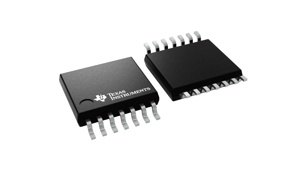
The automotive-qualified device is specified for operation from minus 40 to 150 degrees Celsius and comes in a 14-pin package measuring a nominal 5 by 6.4 mm. TI also lists programmable gain, differential outputs, diagnostics and frequency compensation. Its datasheet describes measurement errors below 0.5% at full-scale currents that can exceed 1,000 amperes after system characterization, but that figure remains dependent on the particular implementation and characterization process.
Production calibration remains part of the system
Dual-axis sensing does not eliminate assembly variation or end-of-line work. TI’s end-of-line calibration guidance says each device is programmed using values matched to a specific busbar geometry. Variations in sensor position, conductor position and device gain can still shift magnetic coupling in the completed inverter.
TI outlines three production-test options: applying balanced three-phase current, energizing individual phases to build a crosstalk matrix, or injecting current between pairs of phases. The methods differ in equipment requirements and diagnostic depth. A full crosstalk matrix can support software compensation during operation, for example, but adds per-unit characterization and processing requirements. Calibration accuracy also depends on the accuracy of the production measurement equipment.
Better current feedback can help a torque-control loop limit torque ripple, unwanted vibration and motor noise. TI associates the TMCS2100-Q1’s reduced displacement error and crosstalk with those benefits, but vehicle-level efficiency and drivability gains will still depend on the complete inverter, motor, controls and mechanical assembly.
Production quantities are available on request, along with an evaluation module, characterization module and reference design. The immediate engineering value is therefore narrower and more concrete than solving every constraint in an 800-volt inverter: the sensor offers a way to reduce vibration-related current-measurement error while preserving a continuous busbar, with system characterization and production calibration still required.
| More aerospace and engineering stories, right in your MSN feed. Follow AMI on MSN |
By Robert McKinney — Editor-in-Chief for AMI’s automotive and mobility coverage, with a mechanical engineering background and a decade reporting on powertrain systems, EV innovation, and global vehicle manufacturing.