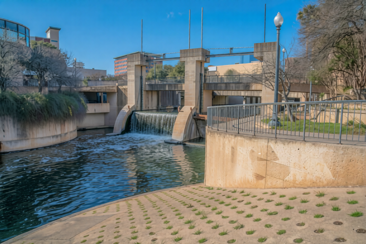
San Antonio Replaces Failed River Walk Gate That Halved Flood Capacity
A worn threaded nut disabled one of two floodgates beneath San Antonio’s River Walk, cutting the dam’s available flood-release capacity in half. The failure turned an already planned equipment renewal into a more urgent systems-integration problem: replace massive machinery inside an operating water-control structure without draining the river or closing the heavily used waterfront around it.

San Antonio and the San Antonio River Authority ultimately replaced both floodgates, which had been installed in 1983. Crews also removed a long-unused screw pump and converted its space into a controlled bypass channel. The River Walk remained in operation throughout the work, leaving most visitors largely separated from a project involving temporary barriers, dewatering equipment, hydraulic machinery and a 650-ton crane.
A small component removed half the available capacity
The failure began inside one gate’s operating gearbox. Threads on a nut had worn down and eventually stripped, allowing one side of the gate to drop. That asymmetric movement damaged multiple components and left the gate inoperable.
Under ordinary conditions, the two gates help maintain the upstream water level that gives the River Walk its controlled appearance. During high water, they can be lowered to release flow downstream. With one gate unable to move, only the other remained available for that flood-release function.
Crews responded by installing stacked steel barriers, known as stop logs, upstream of the failed gate. These held back most of the water and kept the River Walk from losing its normal level. Stop logs were also placed downstream, creating an isolated gate bay that could be pumped dry enough for construction.
The barriers were not perfectly watertight, so a diesel pump continuously managed leakage into the work area. This arrangement illustrates the project’s core engineering tradeoff: instead of draining a much larger section of river, the team created a temporary dry workspace around one component while the surrounding hydraulic system continued operating.
Removal required staged lifts and controlled access
Once the bay was dewatered, crews disconnected the drive shaft that had synchronized the gate’s two operator gearboxes. They then removed the operator support beam and supported the gate with chain slings from the crane before detaching its remaining connections.
Decades-old hardware complicated the work. Large connections had to be pushed, pulled, cut or worked free with hydraulic equipment before the gate could be lifted from the dam. The crane then carried the gate over the river and trees to a staging area on dry ground.
The downtown location imposed its own integration constraints. The project needed space for the crane and removed equipment while preserving a busy pedestrian corridor. Barricades were installed during work periods and removed afterward, while spotters controlled access around heavy lifts. Those measures allowed public activity to continue without mixing visitors with the crane’s operating envelope.
Nearly a year passed between removal of the first old gate and arrival of its replacement, reflecting the design, fabrication, testing and finishing required for machinery of this size. Each new gate arrived in two sections that were joined on site before installation. A detailed lift plan guided the crane as it moved the assembled gate into the existing dam structure.
Hydraulics replace the old electric gate drives
The replacement gates use hydraulic cylinders rather than the old electric-motor and gearbox arrangement. That required modifications to the concrete piers and installation of a hydraulic power unit containing the pumps, valves, regulators and oil reservoir needed to operate the gates.
The first gate was initially lowered only a limited distance during testing because ordinary river flow was not sufficient to permit a full opening without affecting River Walk water levels. After the system operated successfully, crews removed the temporary stop logs and repeated the general process for the second gate.
The project also dealt with another piece of obsolete infrastructure: an Archimedes-style screw pump once intended to lift water from downstream back into the channel above the dam during low-flow periods. A later flood-control tunnel incorporated another way to recirculate water, leaving the screw pump unused for years.
Crews cut out that machinery and rebuilt the pump-room area as a bypass channel with its own control gate. The bypass adds flow capacity and can move water through the relatively stagnant area downstream of the dam, where limited circulation had allowed sediment, debris, algae and mosquitoes to accumulate.
The completed system now has two modern floodgates and the additional bypass. San Antonio restored the capacity lost when the gearbox nut failed, but the larger achievement was maintaining the public waterway while replacing the machinery beneath it. Infrastructure created after the 1921 flood that killed 51 people could not simply be taken offline; the temporary barriers, pumping plan and staged lifts allowed its renewal while it continued serving the city.
| More aerospace and engineering stories, right in your MSN feed. Follow AMI on MSN |
By Thomas Caldwell — AMI’s senior editor for mechanical and mobility engineering, covering vehicle electronics, systems integration, electrification, chassis systems, propulsion, and safety policy.